Graphical UI’s with SVG and React, part 2 — Arcs, Angles, and Transformations
In this mini-series we’re looking at rendering interactive graphical UI’s using components built with React and SVG.
In part 1, Declarative Graphics, we used React to compose simple graphical components from declarative SVG primitives, and covered the basics of the viewBox and the viewport.
Throughout the series we’ll be putting together an interactive floor-plan. In this, part 2, we’re going to add security cameras to the plan and show their field of view, giving us the opportunity to explore arcs, angles, and transformations, along with a useful little digression into alternative coordinate systems.
Let’s start by creating a simple Camera component that we can place inside any Room at a position and orientation we specify. The basic camera will look like this:![]()
How we'd like our camera component to look (zoomed in for clarity)
Our camera shape is straight-forward, and can be composed as a path with 8 straight-line segments joining up 8 coordinates. SVG path elements are powerful tools that create shapes from lines, curves, and arcs and can be stroked and filled just like circle and rect.
Our initial use of path is relatively simple and consists of simple straight line segments using the L command to join up the 8 coordinates of our camera, marked below with black circles.![]()
We’ll make it easy on ourselves by using single digits of a 4x4 square, so our path is easy to create. The path element takes its path data in a d attribute <path d={``}/>.
We begin by telling it to “move” to the coordinate of the first black circle at (0,0), then proceed to draw lines to each of the other absolute coordinates. The final segment is drawn automatically when we “close” the path with Z.
<path
  d={`M0,0 L4,0 L3,1 L4,1 L4,4 L0,4 L0,1 L1,1 Z`}
  fill="black"
/>
Relatively Simple
Path commands such as L can be absolute or relative, designated by upper or lower case respectively, so an alternative way to write the same camera path is to use relative coordinates, like so:
<path
  d={`M0,0 l4,0 l-1,1 l1,0 l0,3 l-4,0 l0,-3 l1,0 Z`}
  fill="black"
/>
Alternatively, a convenient shortcut when drawing lines which are perfectly vertical or horizontal is to use V or H with absolute coords, or v and h with relative coords, yielding yet another alternative way of drawing the same path:
<path
  d={`M0,0 h4 l-1,1 h1 v3 h-4 v-3 h1 Z`}
  fill="black"
/>
Everything in its place
That’s great, we have a nice camera shape, but there’s a problem: we’ve drawn it with the top corner of the camera at the origin of our user-space. How can we place it at a specific location in our user-space? And what if we want to draw more than one Camera at different locations?
One simple option might be to use string interpolation to set the initial position Mx,y to something other than 0,0.
const Camera = ({x, y}) => (
  <path
    d={`M${x},${y} h4 l-1,1 h1 v3 h-4 v-3 h1 Z`}
    fill="black"
  />
);
OK, that works, but the camera is not positioned quite where we want it — we probably meant that x,y is the centre of the camera, so we need to offset it by -50% on each axis. We know that the camera is 4 user-space units wide and 4 units high, so the maths is easy:
const Camera = ({x, y}) => (
  <path
    d={`M${x-2},${y-2} h4 l-1,1 h1 v3 h-4 v-3 h1 Z`}
    fill="black"
  />
);
This is reasonably straight-forward, and because we used relative coords to define the path we only had to do any math for the initial move M operation. However, there’s an alternative way of positioning things without tinkering with the path, which also opens up some exciting new opportunities…
Simply Transformational
Shifting the camera to centre it on the given coordinates involved a reasonably simple change to the path, but things would rapidly get out of hand if we want to, say, rotate the camera by 45 degrees using this approach.
Instead, what if we could design our camera for the simple case of being drawn at the origin and pointing straight upwards, and then apply transformations to position and rotate it as required, avoiding any complicated maths?
In fact we can do just that using the transform attribute, which takes a list of transformation operations and applies them in order. Valid transform operations are:
translate— move horizontally and verticallyrotatescale- skew (
skewXandskewY) matrix(a mathematical expression that consolidates all of the above)
We can specify a list of these operations in a single transform string like this:
transform="translate(20,30) rotate(45) scale(10)"Recall from part 1 that the initial “user-space” specified by the viewBox is the coordinate system in which our SVG primitives are drawn.
By providing a transform attribute with a transform list we are creating a new, nested user-space — a new coordinate system in which the attributed element is drawn.
When applied to a simple element such as a circle, rect, path, etc., the new user-space only applies to that element. However, we can also set a transform on a group <g> element, in which case all elements nested within that group are also drawn in the user-space of the transformed g element.
With this in mind, we can now declare our Camera component such that it can be easily positioned and rotated:
const Camera = ({ x, y, angle }) => (
  <g transform={`translate(${x}, ${y}) rotate(${angle})`}>
    <path
      transform="translate(-2, -2)"
      d="M0,0 h4 l-1,1 h1 v3 h-4 v-3 h1 Z"
      fill="#000"
    />
  </g>
);
This is great — the code that describes the camera’s shape is now entirely static and distinct from the code that positions and orients the camera. We can make this more explicit by extracting a component for drawing the camera body:
const CameraBody = () => (
  <path
    transform="translate(-2, -2)"
    d="M0,0 h4 l-1,1 h1 v3 h-4 v-3 h1 Z"
    fill="#000"
  />
);

const Camera = ({ x, y, angle }) => (
  <g transform={`translate(${x}, ${y}) rotate(${angle})`}>
    <CameraBody />
  </g>
);
Adding Contrast
The camera is quite a dark shape against the dark blue background of our floor-plan, so to increase contrast lets give it a semi-transparent circular “enclosure” that lightens the background.
Because this enclosure is nested inside our camera’s group <g> element it exists within the camera’s user-space, which means we can simply draw it at the origin and it will move and rotate with the camera — result!
Note that we draw the enclosure first, before drawing the camera body, so that the camera body appears on top of the enclosure (on the z axis) and does not get lightened by it.
const CameraEnclosure = () => (
  <circle
    cx="0"
    cy="0"
    r="3.5"
    fill="rgba(255,255,255,0.25)"
    stroke="#fff"
    strokeWidth={0.25}
  />
);

const Camera = ({ x, y, angle }) => (
  <g transform={`translate(${x}, ${y}) rotate(${angle})`}>
    <CameraEnclosure />
    <CameraBody />
  </g>
);
And now we can render multiple cameras in different positions and orientations and see them clearly on our blueprint backdrop:
{
  Array.from({ length: 6 }).map((_, i) => (
    <Camera
      key={`camera_${i}`}
      x={Math.round(Math.random() * 5000)}
      y={Math.round(Math.random() * 3000)}
      angle={Math.random() * 360}
    />
  ))
}![]() Many instances of Camera rotated to different angles
Many instances of Camera rotated to different angles
Field of View
Before we add the cameras to our floor plan, let’s look at showing the camera’s field of view as a segment of a circle centred at the camera origin, looking like this:![]() Camera with 40 degree Field-of-View
Camera with 40 degree Field-of-View
We’re not really trying to model the real world here, just keeping things reasonably simple by defining the field of view as an angle describing the arc, and a distance or range that describes how far the camera can “see”. The API for the FieldOfView component could then just be:
<FieldOfView angle={40} range={500} />Note that we don’t need to specify a position for FieldOfView because it will be nested inside the Camera’s group g element, and therefore drawn in the user-space of the Camera.
We can get a feel for how the props relate to the rendered field of view from the diagram below. Remember that the camera is drawn pointing upwards, so the mid-point of the field of view needs to be directly up the y-axis from the origin.![]() How the range and angle props relate to the rendered field of view
How the range and angle props relate to the rendered field of view
A quick and dirty approximation of the field of view would be a triangle connecting the dots A, B, and C along the dashed lines in the above diagram. We already know the position of A (the origin of our Camera’s user-space), so we just need to work out the positions of B and C, then this approximated path is super-easy to write.
To do that we need to put our math hats on again for some basic trigonometry, but I want to take a little diversion (or a tangent, ahahaha) and talk a little bit about coordinate systems.
If — unlike me — you are a bit of a math whiz, you might already be familiar with Euclidean spaces and coordinate systems, in which case feel free to skim the next section. If not, follow me down the rabbit-hole, I promise its worth it!
Euclidean Coordinate Systems
So far we’ve been working with the familiar Cartesian coordinate system for representing points in a Euclidean space, where [x,y] represents a distance from the origin along the x and y axes. But this isn’t the only way to represent the same point in Euclidean space!
When working with radial UI’s (think clocks, compasses, dials, and just about anything that has symmetry around a centre), there’s an alternative coordinate representation that makes everything waaay simpler to visualise intuitively: a polar coordinate system.
Using polar coordinates, the Cartesian point [x, y] can be expressed instead as a distance from the origin or “pole” and an angle offset from a reference angle, i.e. instead of [x,y] we have [distance, angle].![]() The same point represented in Cartesian and polar coordinates
The same point represented in Cartesian and polar coordinates
In polar coordinates, the positions of points B and C in our field-of-view are intuitively easy to read from the diagram:![]() Polar coordinates are intuitive in radial UI’s
Polar coordinates are intuitive in radial UI’s
Both are at a distance range from the pole. B is at an angle of -angle/2, while C is at angle/2. So the polar coordinates for B and C are [range, -angle/2] and [range, angle/2] respectively. Boom!
Converting from polar to Cartesian coordinates is straight-forward, all we need is a simple function:
export const REFERENCE_DIRECTION = -90;
export const polarToCartesian = (distance, angleInDegrees) => {
  let angleInRadians = toRadians(REFERENCE_DIRECTION + angleInDegrees);
  return {
    x: distance * Math.cos(angleInRadians),
    y: distance * Math.sin(angleInRadians)
  };
};
Note: because of the way sine and cosine work, the reference direction for polar coordinates defaults to being along the positive Cartesian x-axis (or 3 o’clock, or due West if you picture a compass). I find it much more intuitive to work with a reference direction due North or 12 o’clock, hence I’m subtracting 90 degrees to establish my reference direction.
Armed with this function we can calculate the Cartesian coordinates of B and C as simply:
let B = polarToCartesian(range, -angle/2);
let C = polarToCartesian(range, angle/2);
And with that, the triangular approximation of the field of view is easy to write:
const FieldOfView = ({ angle, range }) => {
  let B = polarToCartesian(range, -angle/2);
  let C = polarToCartesian(range, angle/2);
  return (
    <path
      d={`
        M0,0
        L${B.x},${B.y}
        L${C.x},${C.y}
      `}
      fill="rgba(0,0,255,0.25)"
    />
  );
};
Overlaying this approximation on our earlier diagram gives this: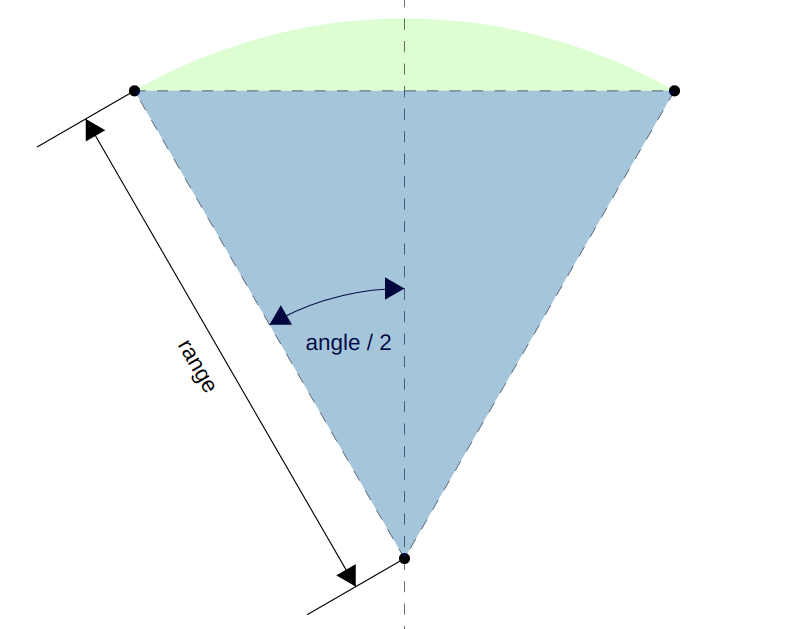
All this talk of polar coordinate systems might feel a bit like overkill, but it really does make things easier to visualise, completely avoids a whole bunch of edge cases (for example if the field-of-view angle is greater than 180 degrees), and where it really shines is when you need to capture user-interaction, e.g. from Cartesian coordinates in mouse or touch events, in terms of the angle and distance — as is often the case with dials, clocks and radial meters and inputs.
If you’re unconvinced of the utility of polar coordinates, a nice exercise might be to try to rewrite the FieldOfView component without using them (and make sure to handle the greater than 180 degrees case). If after that you’re still unconvinced, consider how you might capture input such as in this example circular-slider that I wrote a few years ago.
The arc of our story
Whew! We’ve covered a lot of ground and learned a ton of helpful stuff, so we're all warmed up to take a look at the most convoluted concept in SVG paths — arcs.![]() What does it take to produce this arc?
What does it take to produce this arc?
Arcs are convoluted partly because they are defined — like the other path commands — as starting and ending at specific coordinates (the red dots in the image above). This makes complete sense in the context of a path, but accounts for some of the difficulty in getting to grips with the arc command, which looks like this:
A rx ry x-axis-rotation large-arc-flag sweep-flag x yAn arc is basically a segment of the boundary of an ellipse, so the arc command has to do several things:
- describe the shape and orientation of the ellipse (this is handled by the
rx,ry,x-axis-rotationparameters) - specify the end points of the arc (start point is implicit, end point is specified by
x, y) - select which of the 4 possible arcs that fit criteria 1 and 2 should actually be drawn (
large-arc-flag,sweep-flag)
Point 3 is where things get tricky, so let’s have a quick look at the easy parts first.
Shape and Orientation
The shape of the ellipse that the arc lies upon is described by the first 3 parameters rx, ry, and x-axis-rotation, where rx is the radius on the x axis, ry is the radius on the y axis, and x-axis-rotation is a rotation angle against the x-axis. This is enough to describe the shape and orientation of the ellipse, but not its position.![]() Shape and Orientation, check!
Shape and Orientation, check!
Start and End
The starting point for the arc is implicit, and not part of the arc command itself — it is simply the coordinate at which the previous path command left off. The end-point is supplied as the last two parameters of the arc command, x and y.![]() Start and End points, check!
Start and End points, check!
Which path to take?
We’ve defined the shape of the ellipse, and the two coordinates that the ellipse’s boundary has to pass through, but that isn’t yet enough to describe the arc we want.
In fact, at this point there are 4 possible arcs that we could mean, made from two possible arc-segments of two possible ellipses! Consider the diagram below.![]() Erk! Which arc-segment of which ellipse did we mean?
Erk! Which arc-segment of which ellipse did we mean?
To finally nail down which arc we want to draw, we need to specify which path to take around which ellipse. This is the purpose of the two flag parameters large-arc-flag and sweep-flag which must have a value of either 1 or 0 to specify true or false respectively, and combine to decide which of the 4 possible arcs to draw.
From the diagram above its easy to guess what the large-arc-flag is for — it specifies whether we mean to take the long way around (the larger arc, blue or orange in our diagram) on whichever ellipse, or the shorter arc (pink or green). Setting the large-arc-flag to 1 will send us around one of those two longer arcs (blue/orange), while 0 would pick the shorter (pink/green) arcs instead.![]() possible arcs when large-arc-flag=1 (left), and large-arc-flag=0 (right)
possible arcs when large-arc-flag=1 (left), and large-arc-flag=0 (right)
The sweep-flag is the final deciding factor that selects which arc we meant, and is basically answering the question “should I travel clockwise around the ellipse from the start point to the end point?”
Independently of large-arc-flag, for each possible value of the sweep-flag we again have two possible segments:![]() travel clockwise from start to end when sweep-flag=1 (left), and anti-clockwise when sweep-flag=0 (right)
travel clockwise from start to end when sweep-flag=1 (left), and anti-clockwise when sweep-flag=0 (right)
So we see that the values of large-arc-flag and sweep-flag can combine to determine which of the 4 possible arcs we want to draw, by specifying whether to take the long way around, and whether to move clockwise or anti-clockwise from the start point to the end point.
To achieve the arc we started this section with we want to draw the pink arc, which means taking the small arc in the clockwise direction, so the values we need for large-arc-flag and sweep-flag are 0 and 1 respectively to produce this:![]()
Mind the gap!
One last thing I want to mention, which the mathematically inclined may have spotted, is how on earth would you go about making sure that for the given rx, ry, and x-axis-rotation, the ellipse actually will touch both the start and end point? To illustrate what I mean, consider the path below:
M20,50 L40,50 A10,10,0,1,1,70,50 L90,50Here we’ve specified a horizontal line, followed by circular arc (rx and ry are equal, both 10), that spans the gap from the start point at 40,50 to the end point at 70,50, followed by another horizontal line… but wait, the math doesn’t work out — a radius of 10 means the arc will only bridge between two points that are 20 units apart, but our start and end points are 30 units apart! Logically it seems like this might produce the disconnected path shown below:![]() conflicting arc parameters ... what would it draw?
conflicting arc parameters ... what would it draw?
In fact, the SVG path goes out of its way to handle this for you by scaling the arc until it will fit to your end points — which effectively means that rx and ry are actually just specifying proportional radii to establish the shape of the ellipse, and you don’t have to get into the complicated math of making sure that all of your numbers fit together perfectly.
This is what the path above actually produces:![]() SVG arc radii effectively specify proportions rather than absolute radius values
SVG arc radii effectively specify proportions rather than absolute radius values
Field of View (again)
When we last saw our FieldOfView we’d used a triangle to approximate the shape we wanted. Armed with our knowledge of arcs we can finally complete the intended shape below.![]()
Here's a quick reminder of the arc command:
A rx ry x-axis-rotation large-arc-flag sweep-flag x yWe already know the start and end points of the arc — B and C in the diagram, which we calculated using our polarToCartesian function.
We also know the radii (rx and ry), which are both simply the range prop (although we could just set them both to be 1, given that they only establish the proportions of the ellipse, and our arc is circular rather than ellipsoid).x-axis-rotation has no effect when the radii are equal (because it doesn’t matter how much you rotate a circle, it will always look the same!), so we can leave that at 0.
That just leaves us with those pesky flags to work out, but actually our case is relatively simple.
The large-arc-flag is determined by whether or not our field of view angle is larger than 180 degrees. If it is then large-arc-flag must be 1, and otherwise it must be zero.
Finally, recall that we are drawing our camera pointing directly upwards, with the field of view arc starting at point B at -angle/2, and the arc ending point C at +angle/2. The field of view arc will therefore always start somewhere to our left and end to our right if we’re looking out from the camera’s perspective, and we will always want to travel around the ellipse in a clockwise direction, so the sweep-flag will always be 1.
Our arc command is therefore simple to write using string interpolation:
A${range},${range},0,${angle > 180 ? "1": "0"},1,${C.x},${C.y}And the Camera component, complete with FieldOfView, now looks like this:![]() https://5buhi.csb.app/
https://5buhi.csb.app/
That’s a lot of bang for buck — we have a neat, re-usable Camera component that we can position anywhere in our SVG and point in any direction, and all that in barely 50 lines of declarative code!
Finally we can drop some camera's into our floor-plan, which gives us this little beauty:![]() Floor plans with camera's!
Floor plans with camera's!
Recap
In this post we covered an awful lot of ground:
- Basics of the SVG
<path>element for drawing simple paths using lines, both absolute and relative. - Using the
transformattribute to position, orient, and scale our components separately from the definition of their shape, by applying transforms to an enclosing group<g>element. - A digression into polar coordinates — a useful addition to our toolbox for thinking about and working with radial imagery and UI’s.
- And finally, we looked at the SVG path’s arc command, and broke it down so that we can understand how to tame it.
In “Part 3 — Clip-paths”, we’ll look at how we can keep those lovely camera field-of-view’s from spilling out of the rooms.