Graphical UI's with SVG and React, Part 3 - Clip Paths
In this mini-series we’re looking at rendering interactive graphical UI’s using components built with React and SVG. Throughout the series we’re putting together an interactive floor-plan while working through SVG concepts, starting from the basics and working through some more complicated areas.
If you’re new to React and/or SVG, or you just want to get some context on our ongoing project, you might want to start from the beginning with part 1, Declarative Graphics, where we laid out our basic floor-plan blueprint.
In part 2 we added cameras to our plan and showed their field of view, but there’s a problem: the camera field of view passes through walls and around corners, giving a false impression of what the camera can see.
In this, part 3, we’ll use clip paths to constrain the field of view to the room that the camera is in, preventing it from overflowing into other rooms or outside the floor-plan entirely.
Boundaries
Let’s start with the easy bit: anything in the room should respect the room’s boundaries. We already have geometry for the room that defines the constraints that we want to apply to anything in the room, so how can we apply those constraints to prevent overflow?
The answer, of course, is clip paths. A clip path (defined with theclipPath element) is just what it sounds like: a path that clips any elements to which it is applied, such that only content that falls inside the defined path is rendered.
In SVG we can compose clip paths from any drawable SVG elements, e.g. circle, rect, polygon, path, and even text!
Binocular Vision
For a simple but fun first example, let’s bring back the Pac-Man ghosts from part 1 and use a clip-path to pretend we’re looking at them through binoculars.
First, here’s the scene without clipping, showing our four ghosts on a blue background:
<g>
  <rect x={0} y={0} width="100%" height="100%" fill="blue" />
  <Ghost x={400} y={350} scale={2} colour="red" />
  <Ghost x={600} y={500} scale={2} colour="yellow" />
  <Ghost x={800} y={300} scale={2} colour="cyan" />
  <Ghost x={900} y={450} scale={2} colour="magenta" />
</g>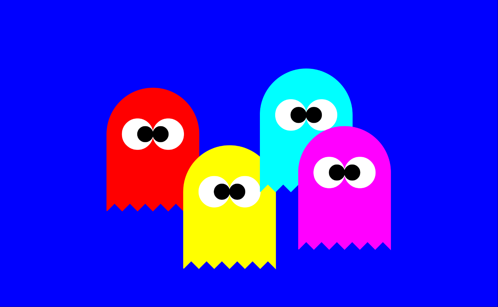
Now let's create our first clip path to constrain the drawing to two adjoining circles in the old movie trope binocular shape.
<clipPath id="binoculars">
  <circle cx={500} cy={400} r={200} />
  <circle cx={800} cy={400} r={200} />
</clipPath>
A couple of things worth highlighting here:
- As you can see, we’ve given the
clipPathan id, which is necessary in order to apply the clip path to another SVG element. - We didn’t stroke or fill the circles — we don’t need to — because
clipPathdoesn’t pay any attention to stroke and fill, it simply takes the entirety of the shapes added to it and allows content to be rendered if it falls within those shapes. In that sense,clipPathis all-or-nothing.
Now all we need to do is set the clipPath attribute on the element we want to clip with the valueurl(#binoculars). In our case we just need to add that to the <g> element containing the ghosts.
<g clipPath="url(#binoculars)">
  <rect x={0} y={0} width="100%" height="100%" fill="blue" />
  <Ghost x={400} y={350} scale={2} colour="red" />
  <Ghost x={600} y={500} scale={2} colour="yellow" />
  <Ghost x={800} y={300} scale={2} colour="cyan" />
  <Ghost x={900} y={450} scale={2} colour="magenta" />
</g>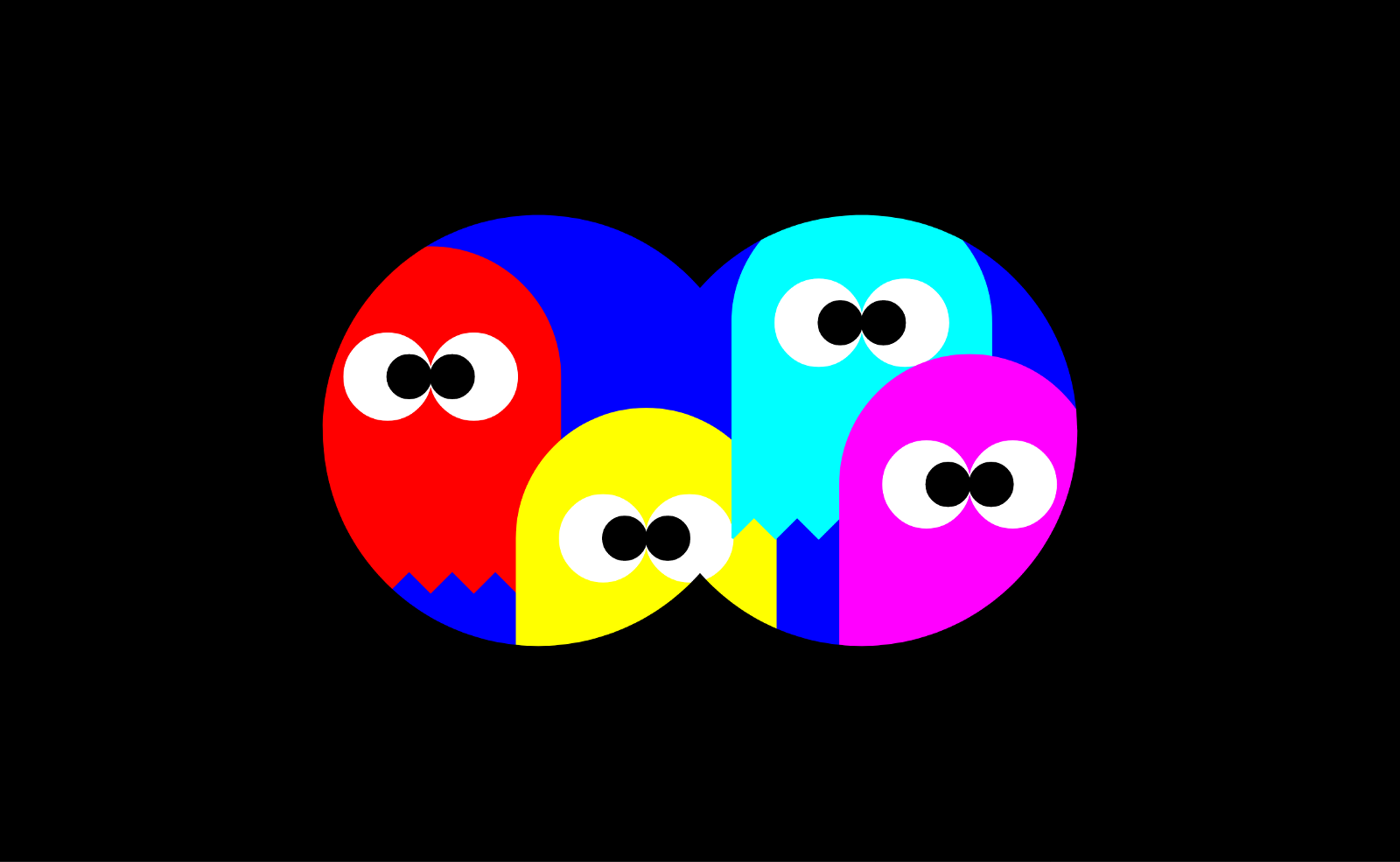
What goes on in the room, stays in the room
Back to the floor-plan. Our Room component currently renders as a group<g> containing walls, corners, and cameras (and I added the room name as red text in the corner of each room). Here’s the current code and its output:
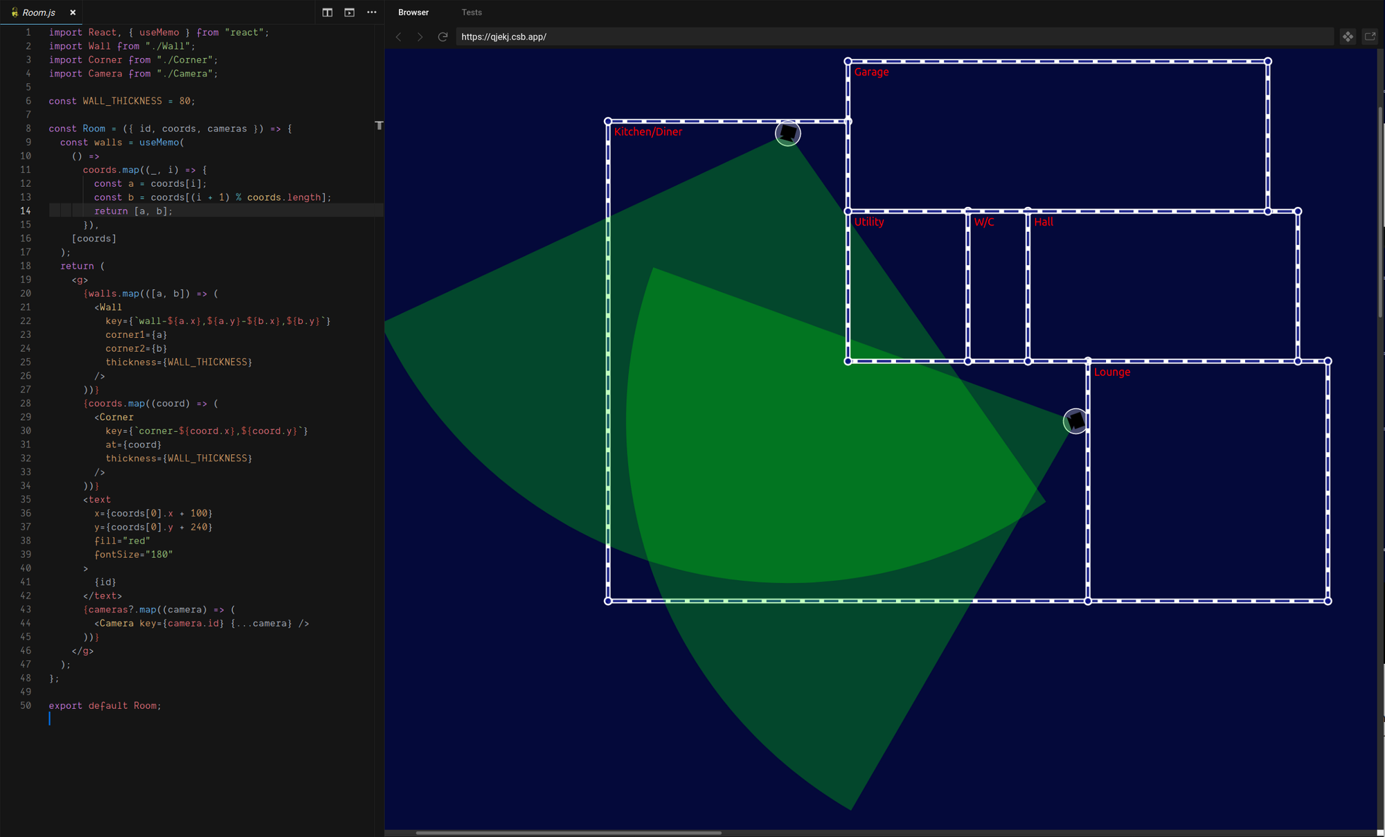
We want to modify this component so that the contents of a Room can no longer render outside the bounds of the room. To do that we want to do two things:
- Change the render order such that the contents of the room (currently really just the camera’s) are drawn first, and therefore are rendered beneath the walls and corners (in z order).
- Render the room contents inside a
<g>element that is constrained by a clip path along the room’s boundaries, so that contents cannot overflow the room.
Step 1 just means pulling the camera’s up to be the first thing rendered inside the Room’s <g> element, but why do we even need step 1? Well, our walls and corners are rendered along the boundary of the room, but they have some thickness and so half of the thickness of the wall falls inside the boundary of the room.
The clip path will prevent contents of the room from being rendered outside the boundary, but would not stop them from rendering over the inner part of the walls, so this is a simple workaround to prevent that. A more satisfying — but more complicated — alternative would be to adjust the clip path to account for the wall thickness, but for now we’ll keep things simple.
Room geometry as clip path
Having pulled our camera’s up to the first-child position in the room, we can nest it in a new group <g> element, to which we will later apply our clip path.
<g>
  {cameras?.map((camera) => (
    <Camera key={camera.id} {...camera} />
  ))}
</g>
Now let’s create the clip path. We need to give it an id so that we can refer to it from the clipPath attribute of the camera group element. Our room data includes an id so we can use that to make up the clip path id, e.g.
<clipPath id={`${id}-content-clip`}></clipPath>To define the shape of the clip path we need to use the room boundary coordinates to construct a solid shape. Our room geometries are just a series of coordinates with no flashy curves or arcs, so while we could use the all-powerful path element we have a simpler alternative in the polygon element.
The SVG polygon element gives us a convenient way to convert our coordinates into a rendered shape: polygon takes a points attribute, which is a space-separated list of comma-separated coordinates, like this:
<polygon points="20,20 40,30 30,30 ..."/>This is perfect for us, because we can simply map our room coordinates array to a string for the points attribute and we’re done!
<clipPath id={`${id}-content-clip`}>
  <polygon points={coords.map(({x,y}) => `${x},${y}`).join(" ")}/></clipPath>
Now all we need to do is add the clipPath attribute to our camera group to apply the clip-path.
<g clipPath={`url(#${id}-content-clip)`}>
  {cameras?.map((camera) => (
    <Camera key={camera.id} {...camera} />
  ))}
</g>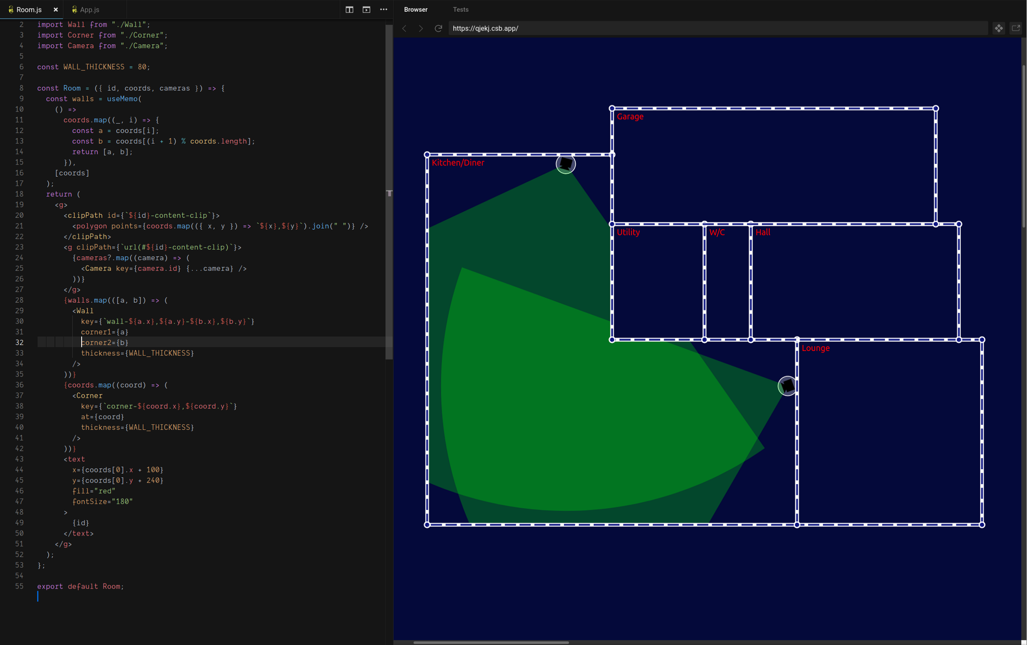
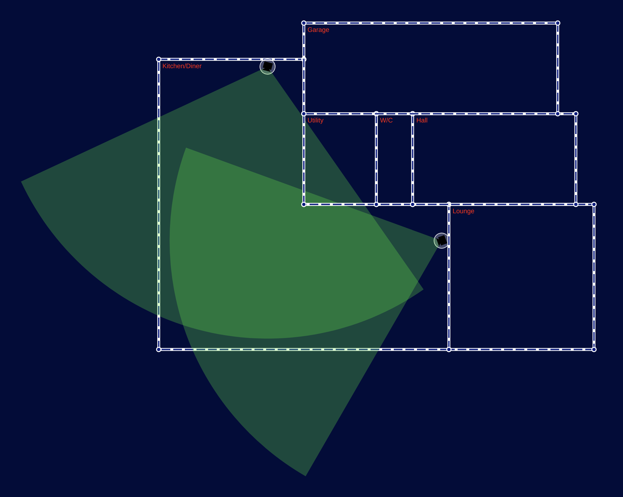
This is great, with some very simple changes we’ve clipped the content of the room so that it doesn’t spill outside the boundary!
Lines of Sight
Look closely at the floor-plan image above though, and you’ll see something’s not quite right. Our cameras can’t see through walls any more, but they can see around corners!
To solve this we’re going to need the camera itself to clip the field of view according to its lines of sight. This will involve creating a more intricate clip-path shape, but most of what follows is just a fun bit of problem solving, so if you’re not into algorithms feel free to skip to the bottom to see the results.
The Disjoint Segment Visibility Problem
To clip the camera field of view to what the camera would actually be able to see accounting for occlusion due to walls blocking lines of sight, we need to solve the Disjoint Segment Visibility Problem where the segments are our walls.
When dealing with large numbers of segments this is typically done with a sweep-line algorithm that projects rays out from the view-point (our camera) at discrete intervals around a full 360 degree sweep, checking for the nearest intersection with a segment at each interval.
One problem with the sweep-line approach is that the use of discrete intervals (e.g. 1 degree) means that the precision is only as high as the chosen interval allows for, and we might produce a field of view that visibly cuts through corners of walls or misses the corner and leaves a small gap.
One way to deal with this would be to use smaller intervals until we get the precision we want, with the trade-off that the smaller the interval the more calculations we need to make.
In our case, however, we know that each room is composed of a very small number of segments (walls) so we can take a different approach: rather than sweep through 360 degrees, we can check only the angles to known segment end-points, which reduces the number of calculations we need to make, and simultaneously allows us to achieve very high precision at little cost.
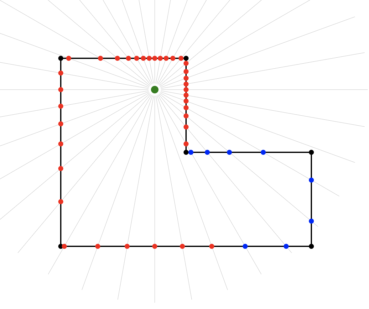
The Visibility Polygon
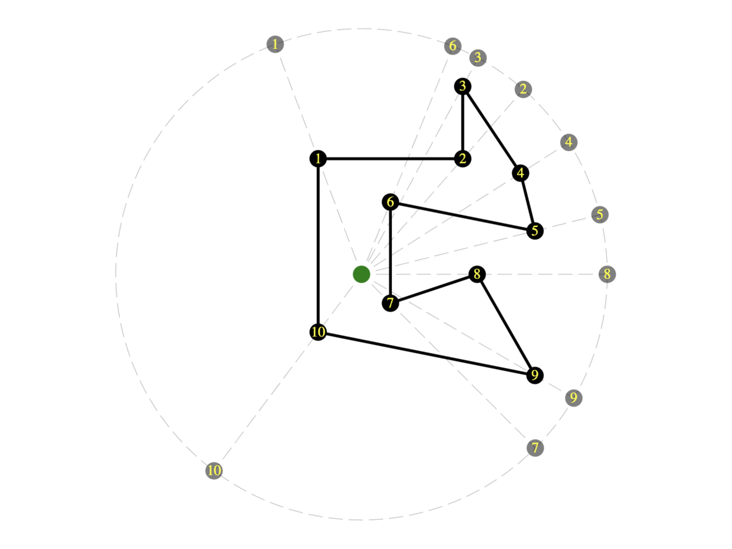
Our task, then, is to create a “visibility polygon” describing the critical lines of sight from the camera position to the nearest walls of the containing room. We’ll use a modified sweep-line algorithm that boils down to some pretty simple steps:
- Find the angle to each wall end-point from the camera
- Reduce to the set of unique angles
- Sort the unique angles into clockwise order
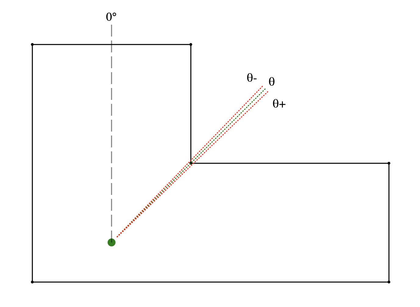
- Insert two new angles
θ-andθ+to either side ofθ, whereθ-is a fraction smaller than (CCW of)θandθ+is the same fraction larger than (CW of)θ. - For each angle in the resulting list, find the nearest wall intersection and add it to our visibility polygon
At step 1, we can find the angle to each wall end-point simply by converting each coordinate from the Cartesian coordinate system to a polar coordinate system with the camera as the origin. The angle part of the polar coordinate is thus the angle to the wall end-point.
Step 2 eliminates any duplicate work, for example where a camera might be looking directly along the line of a wall such that both wall end-points are at the same angle, or in more complex room shapes where distant corners might align with nearer ones along the cameras line of sight.
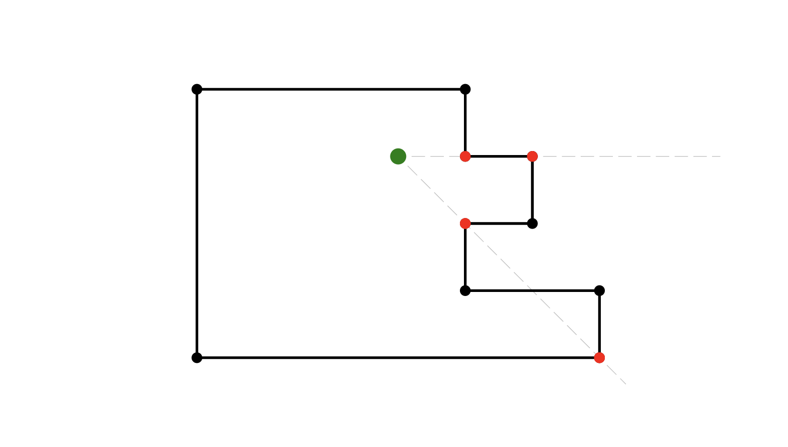
Because rooms can potentially be composed of complicated arrangements of walls, Step 3 is important to ensure that the points of our visibility polygon are arranged clockwise around its boundary to produce a continuous shape from start to finish.
It doesn’t strictly matter whether we sort now or at the end, but it is more efficient to do it now because step 4 triples the number of points that would need to be sorted.
Step 4 gives us the high precision we want — the angles fractionally before and after the angle to each wall end-point are the critical line of sight intervals we need to test in order to get very precise results with no visible corner cutting.
Step 5 converts the collected angles of critical lines of sight into the Cartesian coordinates of our visibility polygon, by finding the nearest intersection of the line of sight with a wall.
In javascript the whole thing looks like this:
const getVisibilityPolygon = (from, cartesianCoords) => {
  // wall corners as indexes into the cartesian coords array
  let walls = cartesianCoords.map((_, i) => [
    i, (i + 1) % cartesianCoords.length
  ]);

  // get all points in polar coords, giving us angles from camera
  let polar = cartesianCoords.map((c) => cartesianToPolar(c, from));

  // reduce to the set of unique angles that we need to test
  const unique = Array.from(
    polar.reduce((r, { angle }) => r.add(angle), new Set())
  );

  // sort into clockwise order
  const clockwise = unique.sort((a, b) => a - b);

  // produce angles slightly CCW and CW of each angle in the list
  const checkPoints = clockwise
    .map((angle) => [angle - 0.01, angle, angle + 0.01])
    .flat();

  // find the nearest intersection with a wall
  return checkPoints.map((angle) => {
    return nearestIntersection(from, angle, walls, cartesianCoords);
  });
}
For this to work we’ll need to add a few more utilities to our geometry toolkit: First we’ll need to modify our polarToCartesian function so that we can pass the camera’s Cartesian coordinates as the origin for the polar coordinates. Second, we need to add the inverse function cartesianToPolar to convert in the other direction.
export const REFERENCE_DIRECTION = -90;

export const degreesToRadians = (degrees) =>
  (degrees * Math.PI) / 180.0;

export const radiansToDegrees = (radians) =>
  radians * (180.0 / Math.PI);

export const vector = (from, to) => ({
  x: from.x - to.x,
  y: from.y - to.y
});

export const magnitude = (vector) =>
  Math.sqrt(Math.pow(vector.x, 2) + Math.pow(vector.y, 2));

export const distance = (from, to) => magnitude(vector(from, to));

export const polarToCartesian = (
  { angle, range }, orig = { x: 0, y: 0 }
) => {
  let angleInRadians = degreesToRadians(angle + REFERENCE_DIRECTION);
  let cartesian = {
    x: range * Math.cos(angleInRadians),
    y: range * Math.sin(angleInRadians)
  };
  return { x: orig.x + cartesian.x, y: orig.y + cartesian.y };
};

export const cartesianToPolar = (point, orig = { x: 0, y: 0 }) => {
  let v = vector(point, orig);
  let range = magnitude(v);
  let angle = radiansToDegrees(Math.atan2(v.y, v.x));
  return { range, angle: angle - REFERENCE_DIRECTION };
};
Finally, we need a functionnearestIntersection that takes a Cartesian coordinate of a point of interest such as our camera location, an angle, and a list of segments (walls) to test for intersection at that angle, and returns the nearest intersection to the point of interest as a Cartesian coordinate.
const nearestIntersection = (from, angle, walls, coords) => { ... }This is going to come down to finding intersections between line segments, where one segment is a wall, and the other is the line of sight — an imagined ray projected out at angle from the camera position — so we will need a function to test whether and where two segments intersect.
Finding the intersection of two line equations (think lines of infinite length) is well-known mathematics, where one possible solution in code looks like this:
export const lineIntersectsLine = ([a, b], [c, d]) => {
  let a1 = b.y - a.y;
  let b1 = a.x - b.x;
  let c1 = a1 * a.x + b1 * a.y;
  let a2 = d.y - c.y;
  let b2 = c.x - d.x;
  let c2 = a2 * c.x + b2 * c.y;
  let determinant = a1 * b2 - a2 * b1;
  if (determinant === 0) {
    // parallel lines never intersect
    return false;
  } else {
    let x = (b2 * c1 - b1 * c2) / determinant;
    let y = (a1 * c2 - a2 * c1) / determinant;
    return { x, y };
  }
};
This gives us the intersection point of the two line equations unless the lines are parallel, and is a step in the right direction, but we need to know that the point of intersection actually lies somewhere on both finite length sub-segments of the line equation (the wall, and the ray from the camera). We can check this by testing that the intersection point lies within the bounds of both line segments:
export const MARGIN_OF_ERROR = 1e-9;

const pointIsOnSegment = ({ x, y }, [a, b]) =>
  x - MARGIN_OF_ERROR <= Math.max(a.x, b.x) &&
  x + MARGIN_OF_ERROR >= Math.min(a.x, b.x) &&
  y - MARGIN_OF_ERROR <= Math.max(a.y, b.y) &&
  y + MARGIN_OF_ERROR >= Math.min(a.y, b.y);
Notice that we’re allowing a tiny margin of error here to account for errors in floating point math. And now we can write a function that tests whether and where two line segments intersect:
const segmentIntersectsSegment = (l1, l2) => {
  let pointOfIntersection = lineIntersectsLine(l1, l2);
  if (
    pointOfIntersection &&
    pointIsOnSegment(pointOfIntersection, l1) &&
    pointIsOnSegment(pointOfIntersection, l2)
  ) {
    return pointOfIntersection;
  } else {
    return false;
  }
};
Which gives us everything we need to complete our implementation of nearestIntersection as follows:
const LARGE_DISTANCE = 1e9;

const nearestIntersection = (from, angle, walls, coords) => {
  let to = polarToCartesian({ range: LARGE_DISTANCE, angle }, from);
  let intersections = walls
    .map(([a, b]) =>
      segmentIntersectsSegment([from, to], [coords[a], coords[b]])
    )
    .filter((intersection) => !!intersection)
    .map((intersection) => ({
      intersection,
      distance: distance(intersection, from)
    }))
    .sort((a, b) => a.distance - b.distance);
  return intersections?.[0]?.intersection;
};
When projecting the ray from the camera i’m using a very large distance instead of the camera’s range, which will give us a visibility polygon defined as points along the walls of the room, regardless whether the camera can see that far. This slightly simplifies the algorithm because it means there will always be at least one intersection for each angle.
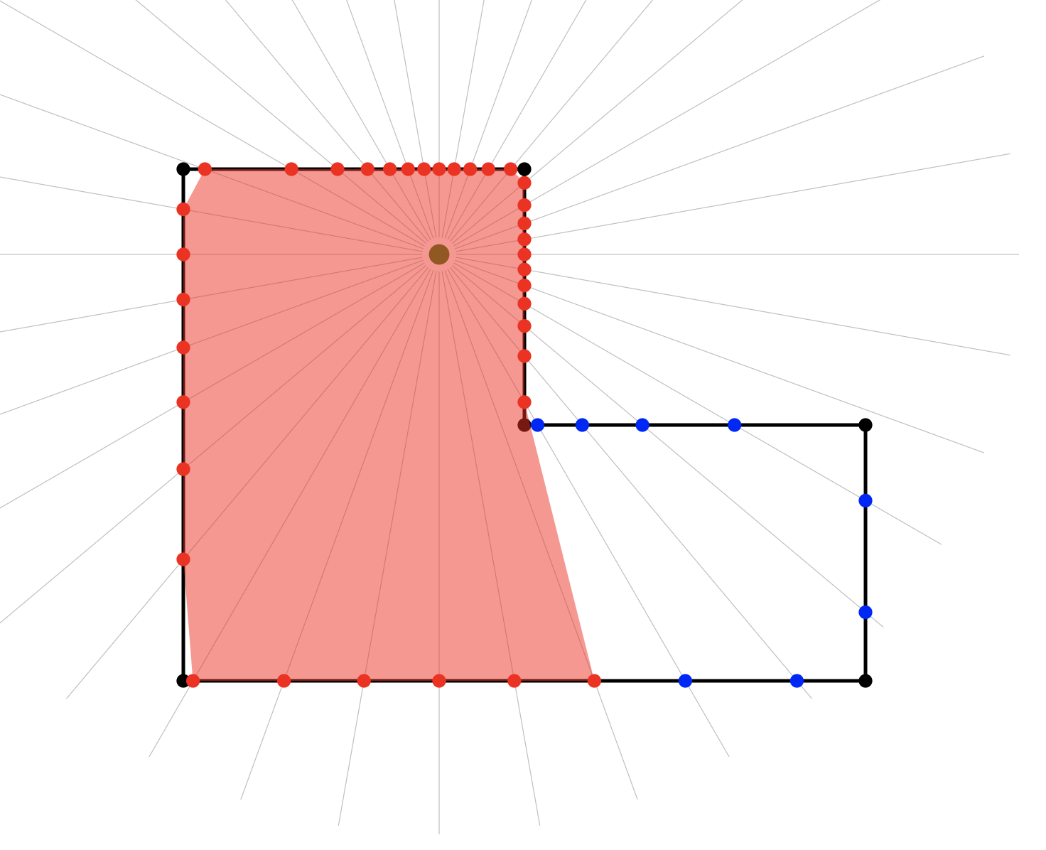
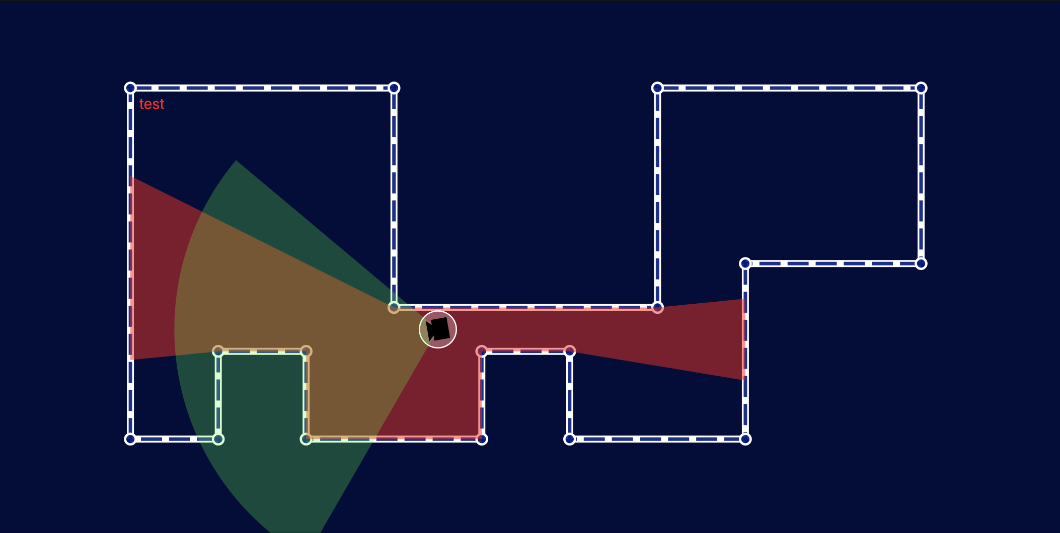
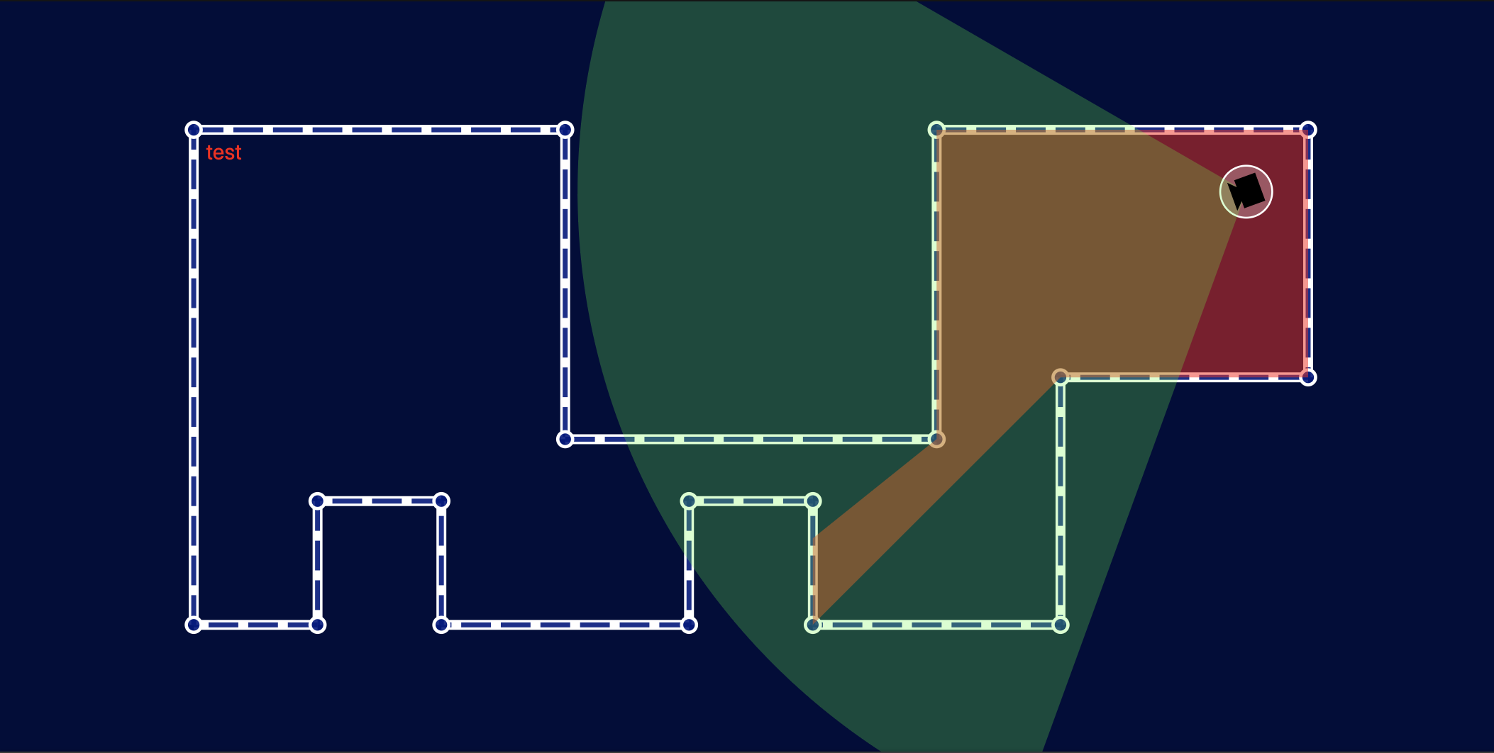
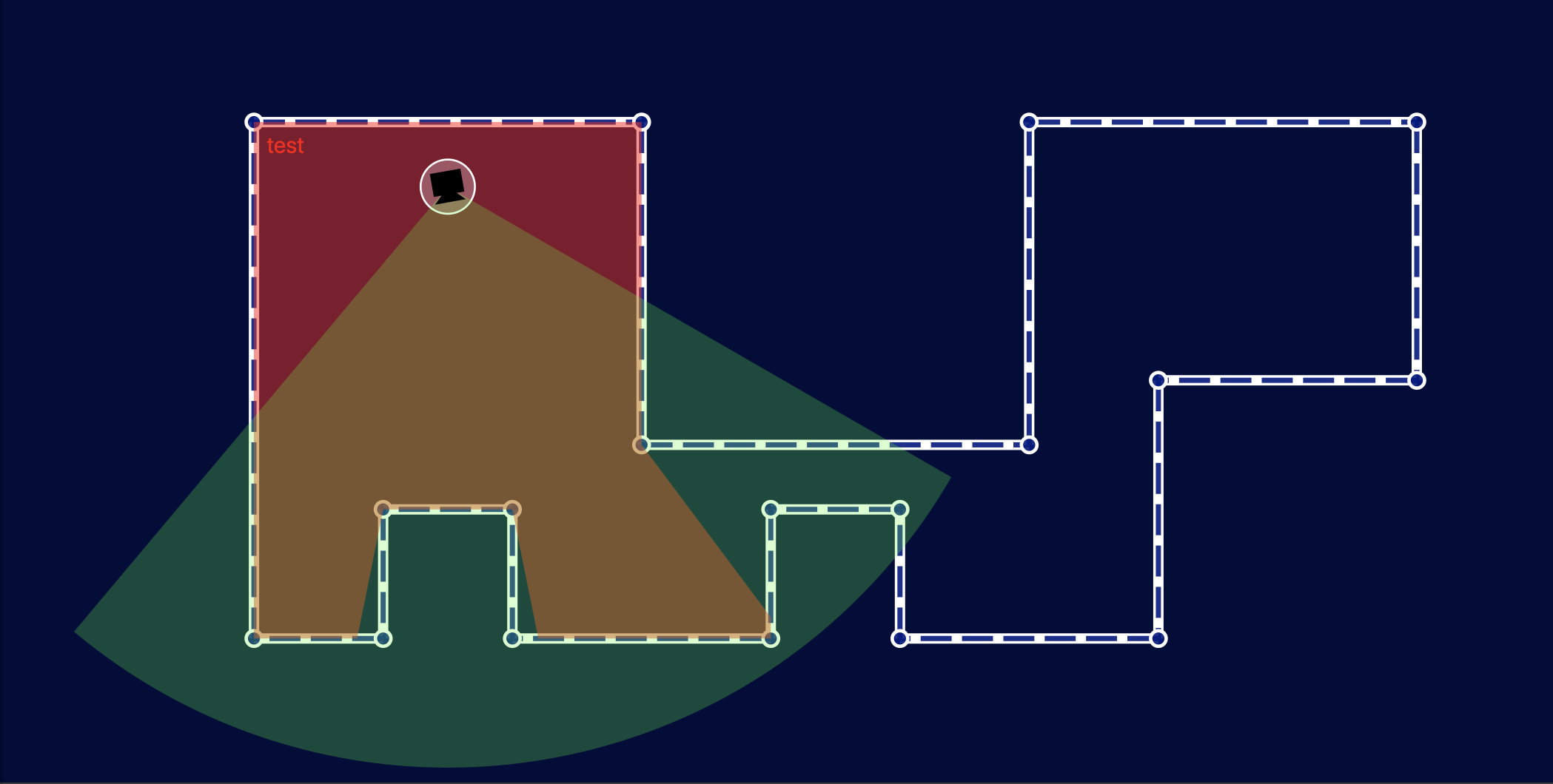
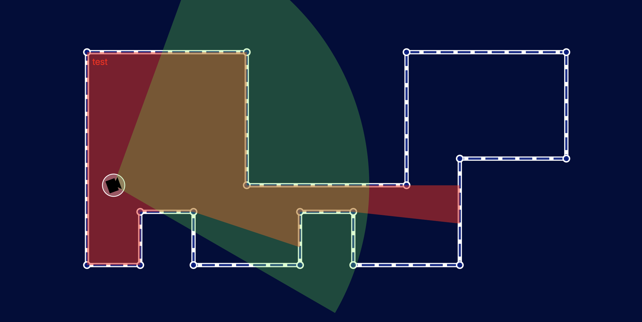
Below you can see what happens when we test this with a more complex room shape and a bunch of different cameras. To illustrate the visibility polygon vs the camera field of view I have not clipped the field of view — instead I’ve drawn both the field of view (green) and the visibility polygon (red) with some transparency so that the intersection (orange) and difference are clearly visible. Once the clip is applied, only the orange part will be visible.
Feeding this back into our Camera component is straight-forward and gives us the following:
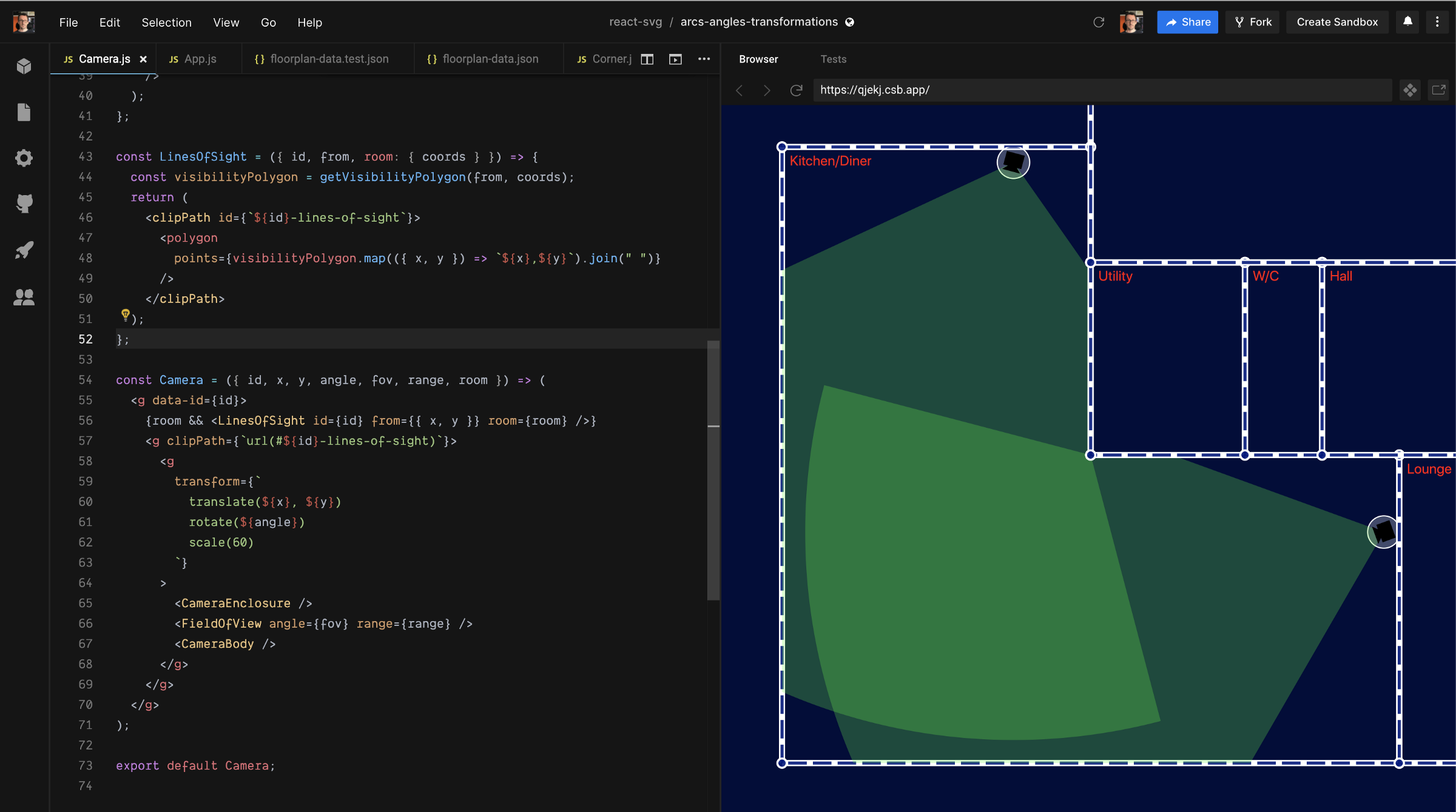
Whew, that got a little heavy, but we now have a clean, simple, and fast mechanism for finding the visibility polygon from any given point in a room, and we can use that visibility polygon as a clip-path to constrain the camera field of view in a realistic manner.
Recap
In this post we learned what clip-paths do, how to compose them from arbitrary SVG shapes and paths, and how to apply them to elements or groups to constrain what gets drawn.
We then took a bit of a dive into some fun algorithms that once again take advantage of alternative coordinate systems to make our lives easier.
In part 4 we’ll look at masks — a more sophisticated method of constraining the rendered output that gives us more control than clip-paths.